More Than Throughput: Next Generation Wi-Fi Testing with Ixia's WaveDevice
by Joshua Ho on March 25, 2016 8:00 AM ESTWi-Fi Basics: L1/PHY Layer
While most of our readers will have likely used Wi-Fi for the better part of two decades - and in my case it has essentially been around most of my life - in practice few people at all know that much about how Wi-Fi works, even within technical circles. Overall, Wi-Fi is a deceptively complex topic for those that are unaware of how it works, as it extends far beyond simple radio transmission principles, especially with the most recent iterations of the technology. Some knowledge can definitely be transferred over from LTE and other cellular technologies, but Wi-Fi is a very different technology in the sense that much of the intelligence has to stay on the device, as opposed to being supplied by a base station or access point. For the most part it’s up to the device to decide what the right physical link rate is based upon the RF environment, when to transmit data, how to roam between access points, how and when to use power save mechanisms, and to proper connection setup between the device and the access point.
Source: Wikipedia By Chetvorno - Own work, CC0
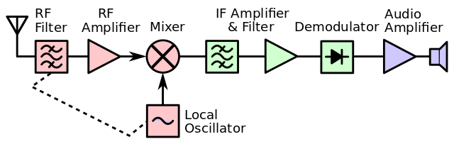
To understand Wi-Fi, we can start at the physical link layer, or Layer 1/L1. Anyone who has done some studying of how radios work will probably see a lot of similarities here as in general every Wi-Fi combo chipset that will ship in a phone is going to have a superheterodyne radio. At a high level, a superheterodyne radio is basically a radio that uses frequency mixing in order to convert the incoming signal to a different frequency to make the signal easier to process.
In the case of this kind of radio, the RF front end on the receive side contains filters, a low noise amplifier to get very weak signals up to usable levels, and a mixer is then used in conjunction with a local oscillator to get the incoming waveform from the signal frequency down to the carrier frequency. There are also likely to be some more filters and amplifiers after the local oscillator as the circuit is dealing with an electric signal (AC) at a much lower frequency, as while it’s pretty easy to get a transistor to switch on and off at 10 MHz it’s pretty much impossible to do the same thing at 60 GHz. From here, the signal can be converted from analog to digital, and also brought down to baseband frequency. For those that aren’t familiar with signal processing, baseband is effectively the frequency from 0 Hz up to the maximum signal frequency (which for Wi-Fi is often going to be the channel width, ranging from 20MHz to 80MHz). When the signal is at baseband, it’s possible to do a lot of signal processing that would otherwise not make a lot of sense, like Fourier transforms.
![]()
Source: Microwaves & RF
On the transmit side, Wi-Fi continues to look relatively similar at the physical block diagram level when compared to pretty much every commercial radio design since the 1940s. Starting at the modem, data is encoded from a digital bitstream into a baseband signal. This signal is then amplified appropriately, upconverted to the signal frequency with the local oscillator again. At this point we're back to the passband frequency that the radio will transmit at. Before the signal is transmitted though, it is fed through more amplifiers like a driver amplifier and filtered again. The signal is amplified again through the power amplifier to get up to a reasonable transmit power for the receiver before it is transmitted through the antenna.
Source: Wikipedia, Bob K
This technically what enables the physical link layer to work, and any issues here can really cause everything to fall apart. In the case of 802.11ac physical layer, the signal is encoded into the carrier using modulation anywhere from BPSK up to 256QAM. We have discussed this before, but the short story is basically that a sinusoidal signal can be decomposed into two sinusoids that are out of phase by a quarter of a period.
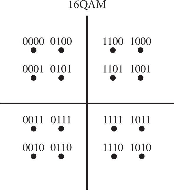
By varying these two components, it’s possible to generate an infinite number of points that represent a binary encoding. Of course, this is limited by the noise present in the received signal, which turns points into a probabilistic cloud.

Source: Keysight Technologies
In addition to this varying of phase, Wi-Fi also splits the channel into narrow subcarriers to maximize throughput. This technique is known as orthogonal frequency-division multiplexing, and is used in a number of technologies like LTE as well.
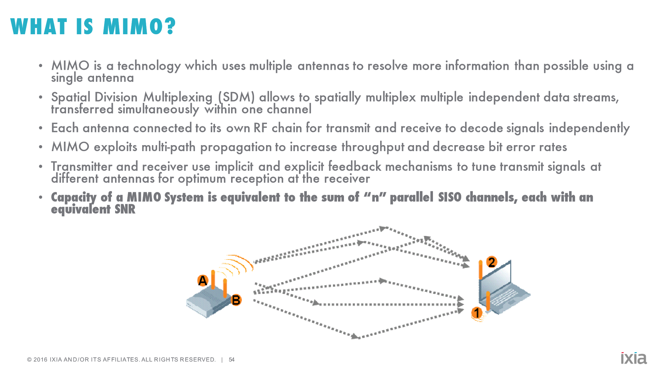
The other technique that is worth knowing about is Mulitiple Input and Multiple Output (MIMO) and Multi-User MIMO (MU-MIMO). In both cases, multiple antennas are used to enable additional throughput by utilizing multipath transmission. MU-MIMO in turn takes this a step further by using precise beamforming in order to spatially multiplex transmission and reception. While the concept is relatively simple, actually implementing this is difficult to say the least, which is why MU-MIMO Wi-Fi implementations have only been shipping for about a year or so.
Source: 3G4G Blog, NTT
This aspect of Wi-Fi is known as the Physical Medium-Dependent layer, or PMD layer. There are more aspects that could be discussed regarding the physical link layer, but in the interest of not making things any more confusing we’ll stop here and talk about what aspects of the physical layer WaveDevice is actually capable of testing. With every packet, WaveDevice is capable of reporting a number of statistics about what’s happening at the physical link layer. Importantly, this includes the constellation error, by showing the average magnitude of the deviation of the actual I/Q position relative to the theoretical I/Q position for a given encoding. It’s also possible to look at how well the device is constraining its transmission to specific bands/channels, and whether the device is transmitting excessive levels of power, although transmit power limits is really more the realm of FCC compliance than anything else.
As a result, when we’re looking at relative Wi-Fi performance, we can actually start to make determinations about whether the problem with a device’s Wi-Fi performance is because it’s just not transmitting data properly and causing data corruption, or if it’s something happening at the software level. While the physical layer is critical, if you subscribe to the OSI model of networking then there are six layers above it that need to work as well to make sure that your cat pictures load as they should. So next we'll take a look at the data link layer to better understand how Wi-Fi works and what WaveDevice is capable of testing there.


44 Comments
View All Comments
JoshHo - Saturday, March 26, 2016 - link
I was aware before the testing that the Pixel C had something wrong with WiFi, but the goal was to try and separate software issues from hardware ones.It was subjectively obvious but difficult to understand what was causing the problems in a reproducible manner.
at80eighty - Saturday, March 26, 2016 - link
Have to concur with everyone. Happy to see anandtech still keeping that edge to their content. Great work Joshua.mannyvel - Sunday, March 27, 2016 - link
We have one of these systems at work, and you have to be a wifi genius to use it.That said, what our guy said was this: test your throughout with multiple clients at multiple distances. There also some subtleties about wifi that are odd. One is that the anount of airtime that a given adapter uses is more important sometimes than its actual speed. There is only so much airtime, and a badly behaving adapter that's further away will prevent faster devices with better signal from using the AP because of how PHY rates are negotiated (not sure what the term is). Basically an adapter further away will scream louder and more slowly to see if the AP can hear it - but the slow screaming takes airtime away from the faster devices that have better signal.
Also, since it's RF more clients means more interference. I suspect you will find, as we did, that all your wifi testing has been completely wrong for pretty much forever. With the ixia stuff you can tell how bad your AP really performs in, say, and apartment-like configuration.
One more confounding factor is not all chips and drivers behave consistently. An AP that works great with Windows 10 and an atheros chipset may work crappily with the same chip in win7...as you've seen in the iPad Pro tests.
bman212121 - Monday, March 28, 2016 - link
I agree 100% with everything mannyvel said. One of the biggest hurdles people face is range vs density. Everyone thinks that throwing a bigger antenna will give you better wifi and that having an AP with increased range is a good thing. In reality, most APs these days are turned down in power so they match closer to the clients capabilities, and in the case of roaming a minimum RSSI is enforced. Only having "1 bar" hurts overall performance more than having a second AP that can provide higher signal strength. We used to have one high powered Aironet that could cover a huge area. In order to increase performance you might take down that one AP and put up 3 in it's place to get the proper coverage while getting the performance you need.I'd really be interested in some minimum RSSI tests. A great performing antenna might not have the highest power, but you can easily make up for power by having better sensitivity. Even APs of the same power output will have different receiving abilities, and higher end APs can pickup and work with much weaker signals and still maintain solid connections.
skavi - Sunday, March 27, 2016 - link
Holy shit, I can't wait for these WiFi performance and roaming tests for more devices. This is so important, but there is rarely any information specific to devices. My S6 is never able too roam correctly and forces me to reconnect each time I move somewhere, maybe these kinds of tests will pressure OEMs into paying more attention to these issues. It seems Apple at least has gotten it down.Powervano - Monday, March 28, 2016 - link
Very nice and informative article!Could you please test Surface Book and Surface Pro 4 using the WaveDevice? Would be nice to shed some light around the Wi-Fi issues on these devices.
Conficio - Monday, March 28, 2016 - link
Thanks Josh,you are on your way to become a hero for mobile device users. I appreciate the hard work flowing into this article.
I wonder which parts of this stack are software updatable? As there is talk of the Pixel-C having a broken Wifi, is there hope it gets fixed by a software update? In the same interest did I miss the specification of the exact relevant software versions on the devices?
P.S.: The Baseband package on my device influences WiFi or is it only for the WAN portion of my Android device?
cuyapo - Monday, March 28, 2016 - link
Great article, thanks! One thing only:CSMA/CA = Carrier Sense Multiple Access with Collission Avoidance
James5mith - Tuesday, March 29, 2016 - link
Still reading through the article, but it's worth noting that SmallNetBuilder has also switched to this test setup for wireless testing going forward. Interestingly the one thing this doesn't take into account is antenna design. While it's great to test throughput vs. attenuation/power/etc. None of that takes into account if the antenna is poorly designed, oriented incorrectly, etc. It does give a good baseline to work from though. And it should help people track down problems for wifi if they are using a router that tests solidly without taking factors like antenna design into account.James5mith - Tuesday, March 29, 2016 - link
http://www.smallnetbuilder.com/wireless/wireless-f...