Gigabyte Z77X-UP4 TH Review: Thunderbolt Times Two
by Ian Cutress on September 17, 2012 11:00 AM EST- Posted in
- Motherboards
- Gigabyte
- Z77
- thunder
Now that the exclusive license Apple had for Thunderbolt has expired, since Computex 2012 we have seen a number of motherboards destined for PCs with a Thunderbolt connector. Thunderbolt on a motherboard is still an added luxury, adding some $40 to the cost of the board to the user, though that can pale in comparison to the cost of Thunderbolt devices and storage. Despite all this, Gigabyte’s foray into the Thunderbolt world is initiated in part by the board we are reviewing today – the Gigabyte Z77X-UP4 TH. Using the Z77 chipset we get a motherboard with two Thunderbolt ports, but it also has the enhanced power delivery brought about by Ultra Durable 5.
Gigabyte Z77X-UP4 TH Overview
Like many Gigabyte boards in the Z77 range, there are very few issues with the Ivy Bridge platform in Gigabyte’s hands. Due to MultiCore Enhancement, CPU performance matches that of other Gigabyte and ASUS products this generation, and the Z77X-UP4 TH comes with the two major additions – a two port Thunderbolt controller, and IR3550 ICs to help with the power delivery. As we saw on the Gigabyte X79S-UP5, these ICs do help with power consumption assuming the cost can be justified.
Visually, the board does look a little empty with smaller heatsinks, a gap left for an mSATA drive and some empty IO, but we do have a classic three-way PCIe device implementation such that with an Ivy Bridge processor, the board can run x16/-/-, x8/x8/- or x8/x4/x4 in PCIe 3.0 mode. We lack any extra SATA ports, with only those provided by the chipset being used, and the back panel uses only USB 3.0 – two from the chipset and four from a VIA VL800 controller. The other two USB 3.0 ports that the chipset provide are used for an onboard USB 3.0 header.
In terms of extra hardware and controllers beyond the chipset standard, we are hard pushed to find anything special beyond the Thunderbolt controller – sure there is a USB 3.0 VIA VL800 chip, but the audio is a Realtek ALC892 and the Ethernet is a Realtek 8111. The iTE chips onboard give us access to a combination PS/2 port and a COM port as well. But the lack of extra SATA ports is perhaps a little strange for a UP4 product.
Performance on the Z77X-UP4 TH comes on par with the other Gigabyte motherboards tested. This is due to the fact that the Z77X-UP4 TH enables MultiCore Enhancement when XMP is enabled, as per our standard testing methodology. This gives our test bed an extra 200 MHz under full threaded load, which benefits all CPU intensive tasks. Power consumption, due to the use of IR3550 ICs, is low compared to most Z77 motherboards we have tested, and the third PCIe 3.0 slot at performs well with a PCIe 3.0 GPU plugged in.
The only question mark comes down to the price. Thunderbolt and Ultra Durable 5 are, to quote a famous brand, ‘reassuringly expensive’. Thunderbolt adoption in the PC market is quite low right now due to the lack of competitive pricing, so having two ports on board for up to twelve devices is a bit overkill. This limits the Z77X-UP4 TH more into a niche target segment. Though if you have 6-12 TB devices, then this is a nice board to consider. For all other usage scenarios, your $190-$200 might be worth investing in a Z77X-UD5H.
Visual Inspection
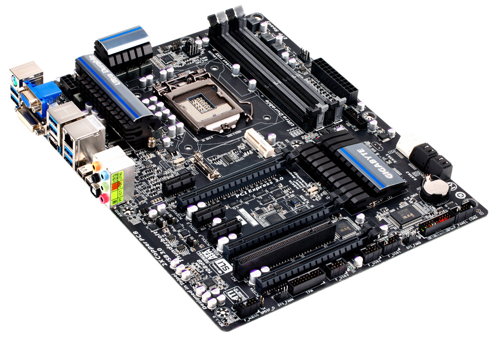
One of the benefits of using the IR3550 ICs in the power delivery is that because each one is rated up to 60 amps, this means fewer phases are needed on board. Having fewer phases means saving energy and cost, but also results in smaller heatsinks, especially when we consider the IR3550s have unique IP to help keep cool. This reduction in the number of phases along with the smaller heatsinks gives the socket area of the Z77X-UP4 TH a lot of room. Almost every air cooler under the sun should fit on this motherboard, even a NoFan. (Actually, the NoFan will probably impinge on the memory slots, requiring low profile memory).
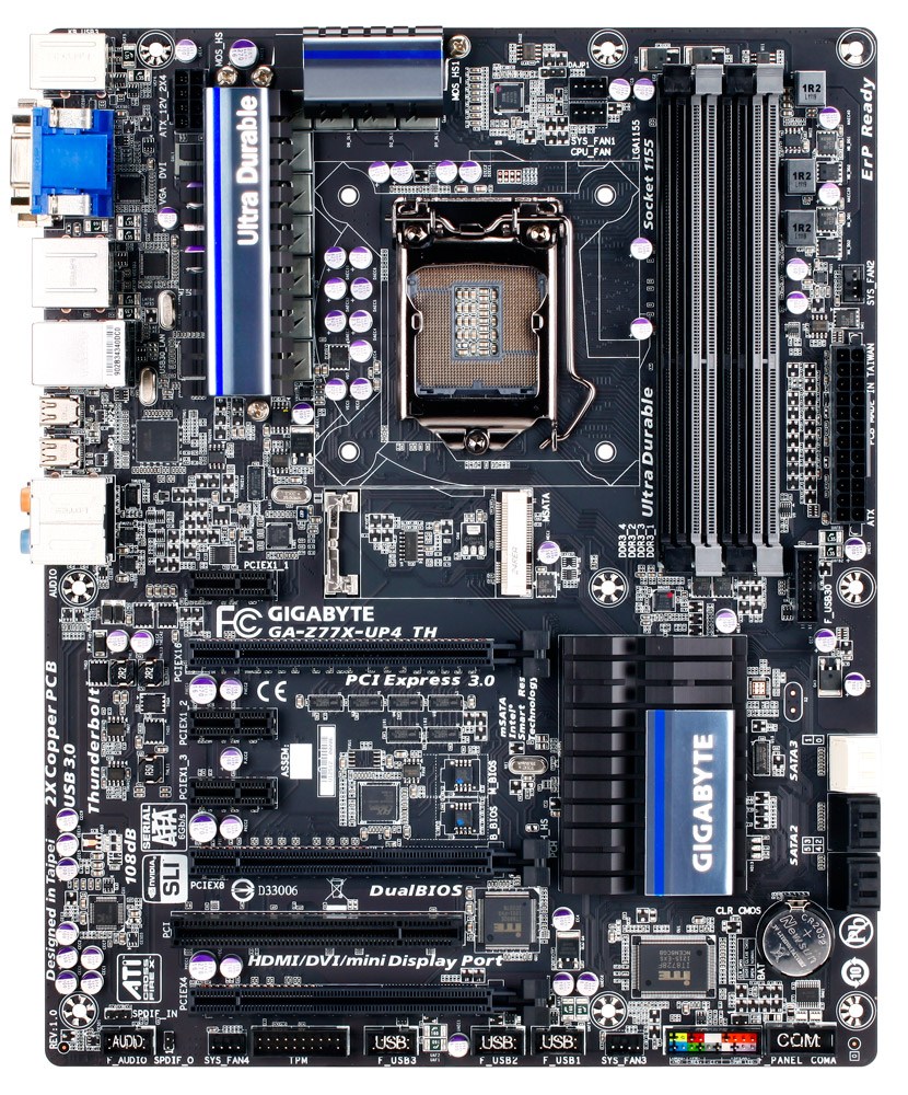
The heatsinks are set away and to the left and the top of the socket area – the right hand side has memory up against the Intel specification distance, but to the south we have a larger empty space than normal due to the mSATA location and the movement downwards of the first full length PCIe slot. For fan headers the CPU area has access to three in the immediate vicinity – two to the top right of the socket (both 4-pin, one CPU and one SYS), and another just above the 24-pin ATX connector (4-pin, SYS). The other two fan headers on board are found on the bottom, again 4-pin and also SYS headers.
The right hand side of the board is empty compared to a lot of other Z77 boards we have seen – from top to bottom there is a 4-pin SYS fan header, the 24-pin ATX power connector, a USB 3.0 header (powered by the chipset), two SATA 6 Gbps ports in white and four SATA 3 Gbps ports in black. One of these black SATA 3 Gbps ports shares routing with the mSATA, meaning only one of them can be used at a time. The chipset heatsink has nothing extra in the way of controllers to cool, so it is relatively small taking care of the chipset chip itself.
The south side of the board gives us front panel audio (found at the back of the board case wise – this confuses me a little), a SPDIF output header, a 4-pin SYS fan header, a TPM header, three USB 2.0 headers, another 4-pin SYS fan header, front panel connections and a COM port header. Ideally I would think that the COM port header and the front panel audio header should be swapped. It is also interesting to note that this PCB has the old ‘ATI CrossFireX’ logo stamped on it, rather than the new AMD one we see on other products.
The PCIe layout is set up to give maximum cooling for a dual GPU setup, despite being configured for a tri-GPU configuration. From the top we have an x1, x16 (x8 in dual and tri), x1, x1, x8 (x4 in tri), PCI and x4. Placing a GPU in the bottom slot could potentially restrict the bottom headers and any cables inserted.
It is worth noting on the board that a few minor details are not present – neither power/reset buttons nor a debug LED are provided. Both of these features are prevalent to testers, overclockers and system builders dealing with overclocked configurations. There is a small BOM cost for applying such additions, but it could save hours of headaches if a stick of memory fails.
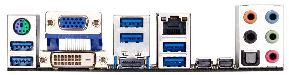
The IO back panel features a combination PS/2 port, video connections (VGA, DVI-D and HDMI), six USB 3.0 ports in blue (two from the chipset, four through a VIA VL800 controller), a gigabit Ethernet port (Realtek), two Thunderbolt ports, an optical S/PDIF output and audio jacks. The two Thunderbolt ports are powered by a single DSL3510L chip, which means peak bandwidth between the ports will combine to a maximum of 10 Gbps, rather than 10 Gbps each. This is also dependent on the PCIe devices connected in the board. However, both ports will support a TB display each, making a maximum of four video outputs possible (VGA, DVI or TB2, HDMI, TB1).
Board Features
| Gigabyte Z77X-UP4 TH | |
| Price | Link |
| Size | ATX |
| CPU Interface | LGA-1155 |
| Chipset | Intel Z77 |
| Memory Slots |
Four DDR3 DIMM slots supporting up to 32 GB Up to Dual Channel, 1066-1600 MHz |
| Video Outputs |
VGA DVI or TB2 HDMI TB1 |
| Onboard LAN | Realtek 8111 |
| Onboard Audio | Realtek ALC892 |
| Expansion Slots |
1 x PCIe 3.0 x16 (x8 in dual) 1 x PCIe 3.0 x8 (x4 in tri) 1 x PCIe 3.0 x4 (when IVB CPU is used) 3 x PCIe 2.0 x1 1 x PCI |
| Onboard SATA/RAID |
2 x SATA 6 Gbps (Chipset), RAID 0, 1, 5, 10 4 x SATA 3 Gbps (Chipset), RAID 0, 1, 5, 10 1 x mSATA 3 Gbps (disables SATA2_5) |
| USB |
4 x USB 3.0 (Intel) [2 back panel, 2 onboard] 4 x USB 3.0 (VIA) [4 back panel] 6 x USB 2.0 (Intel) [6 onboard] |
| Onboard |
2 x SATA 6 Gbps 4 x SATA 3 Gbps 1 x mSATA 5 x Fan Headers 1 x USB 3.0 Header 3 x USB 2.0 Headers 1 x COM Header 1 x TPM Header |
| Power Connectors |
1 x 24-pin ATX Power Connector 1 x 8-pin CPU Power Connector |
| Fan Headers |
1 x CPU (4-pin) 4 x SYS (4-pin) |
| IO Panel |
1 x PS/2 Combination Port 1 x VGA 1 x DVI-D 1 x HDMI 6 x USB 3.0 1 x Realtek GbE 2 x Thunderbolt 1 x Optical S/PDIF Audio Jacks |
| Warranty Period | 3 Years |
| Product Page | Link |
Despite Thunderbolt and IR3550 ICs onboard, we are lacking much grunt in the design. No extra SATA, no Power/Reset buttons or debug LED, Realtek Audio+NIC. It is easy to visualize the design team being told to create a board ‘with Thunderbolt and Ultra Durable 5’, but being given a tight budget to work within. However the usage scenario for the user has to be on the Thunderbolt design to make the purchase worthwhile – in essence the Ultra Durable 5 power delivery is an added extra. I bet a Z77X-UD4 TH would sell just as well if not better than the Z77X-UP4 TH.


15 Comments
View All Comments
IanCutress - Monday, September 17, 2012 - link
I have access to a TB device, but it is only the two-bay Little Big disk with a pair of Intel Drives. Can't really stress the TB implementation in terms of peak speeds, and in our copy test it can get anything from 1.1 seconds to 3.3 seconds depending on if the wind is blowing, or the tides are in (very unpredictable).When I can get a 4-bay TB device in, I will fill it with 500MB/s+ SSDs and get down to testing. Unless there is a specific test you would like me to do (4K et al).
Ian
repoman27 - Monday, September 17, 2012 - link
I am very curious about a couple points, however they are not the easiest scenarios to test.Firstly, GIGABYTE depicts the ability to support a total of 12 connected Thunderbolt devices plus 2 displays, or 6 devices AND 1 display per port. [ http://www.gigabyte.com/microsite/306/images/thund... ] This seems to fly in the face of what we have been told by Apple and Intel about supported topologies, i.e. "up to a total of 6 devices, including up to 2 high resolution DisplayPort v1.1a displays". Can a single Cactus Ridge DSL3510L really handle that many devices? Is there some difference in implementation between Windows and Mac OS?
GIGABYTE also claims a full 10 Gbps of PCIe bandwidth from each port. Now I would also doubt that claim, and in the article you indicated this wasn't happening with a single DSL3510L. However, Anand achieved 1380 MB/s by using both Thunderbolt ports during his review of the MBPR, which also uses just one DSL3510L controller. Now ultimately this controller is bound by its PCIe 2.0 x4 back end, which should limit it to around 1600 MB/s of payload throughput, but breaking the 1000 MB/s barrier would seem to imply that there is more than one PCIe to Thunderbolt protocol adapter in these Cactus Ridge chips. This would be significant if true. Any chance you could lean on it hard enough to find out?
goinginstyle - Monday, September 17, 2012 - link
I agree about the need for TB testing as I have had nothing but issues with this board and a Seagate GoFlex attached on one port and a Apple TB 27" monitor on the other port. The monitor will flicker badly at times (does not happen on a competing board and a MacBook Pro) while the Seagate drive will "disappear" and requires a power on/off before being recognized again.thewhat - Tuesday, September 18, 2012 - link
It would be great if you could test with Speedfan whether the fan speed can be controlled independently for every header.NiggaASD - Sunday, December 9, 2012 - link
Ian, I think you are wrong about Gigabyte manipulating CPU voltage readings. The voltage reading 1.068 V is probably not CPU vcore, it could be VTT(VCCIO) voltage. It is known that some GB motherboards have this "feature", that they show VTT voltage in CPU-Z. For example, my GA-P67A-UD3P-B3 board shows 1.092 V in CPU-Z as vcore when I have set VTT to 1.1 V in BIOS.